 (+035) 527-1710-70
 NEWSLETTER


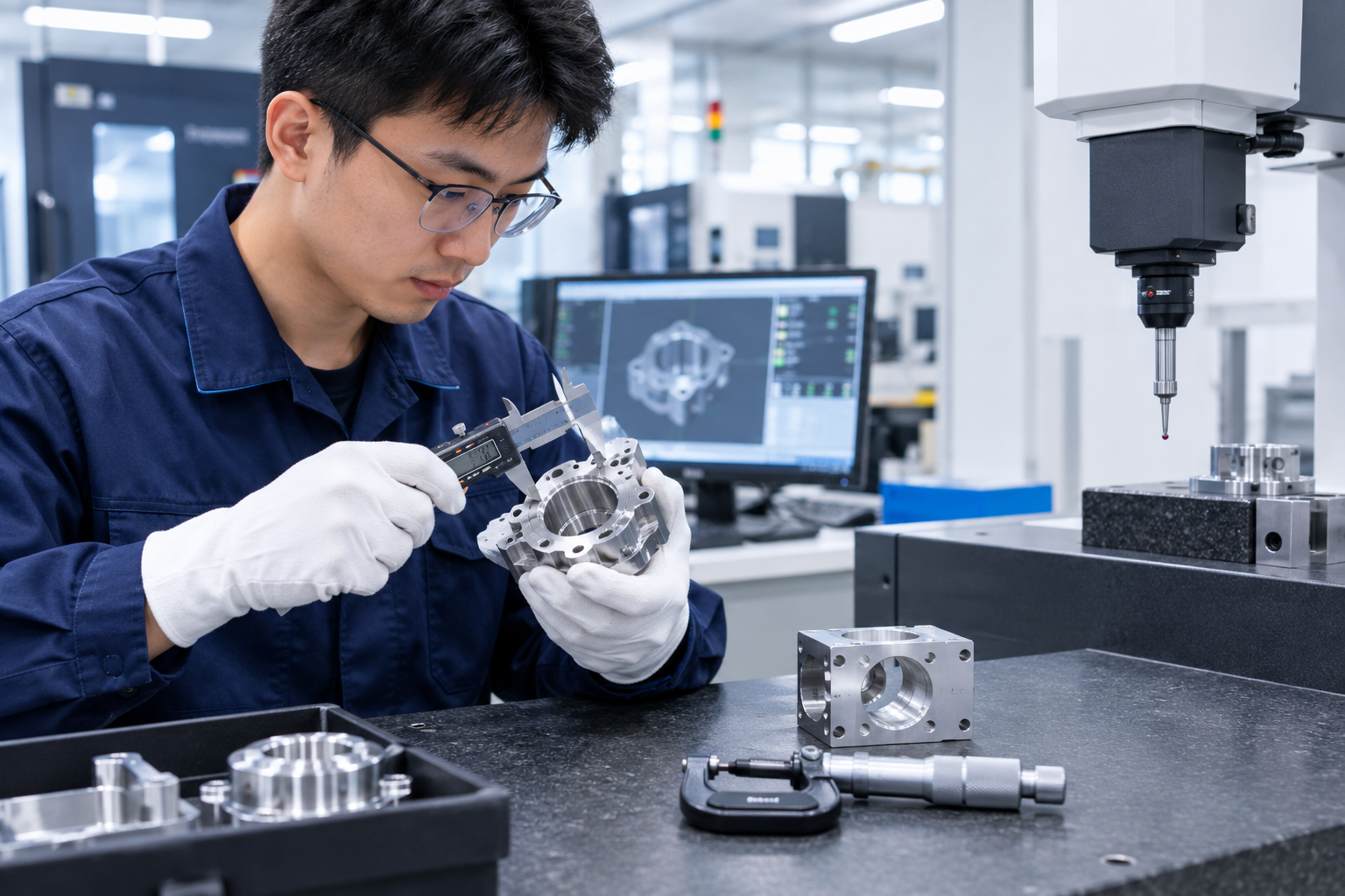
Precision is one of the key advantages of CNC machining, but producing an accurate part is only one part of the manufacturing process. Proper inspection is also essential to verify that the finished component meets the required dimensions, tolerances, surface finish, and functional requirements.
CNC machining inspection uses a combination of measurement tools, inspection equipment, and quality control procedures to compare finished parts against engineering drawings and CAD models.
In this guide, we’ll explain the most common CNC machining inspection methods, measurement tools, quality control processes, and how to determine the right inspection requirements for your project.
What Is CNC Machining Inspection?
CNC machining inspection is the process of measuring and evaluating a machined component to determine whether it meets specified engineering requirements.
Depending on the part, inspection may include:
- Dimensional inspection
- Geometric inspection
- Tolerance verification
- Surface finish inspection
- Visual inspection
- Material verification
The level of inspection required depends on the part’s design, application, tolerances, material, and production requirements.
Why Is Inspection Important for CNC Machining?
Even with modern CNC equipment, manufacturing variations can occur.
Factors such as:
- Tool wear
- Machine calibration
- Material behavior
- Temperature
- Workholding
- Machining conditions
can affect the final dimensions of a component.
Inspection helps identify these variations before parts are delivered or assembled.
For critical components, proper inspection can help prevent:
- Assembly problems
- Functional failures
- Dimensional inconsistencies
- Production delays
- Material waste
Common CNC Machining Inspection Methods
Different inspection methods are suitable for different types of parts and requirements.
1. Visual Inspection
Visual inspection is one of the simplest quality control methods.
Inspectors check the part for visible defects such as:
- Scratches
- Burrs
- Cracks
- Tool marks
- Surface damage
- Improper finishing
Visual inspection is usually performed alongside dimensional inspection rather than as a replacement for it.
2. Dimensional Inspection
Dimensional inspection verifies the physical dimensions of a component against the engineering drawing or CAD model.
Common measurements include:
- Length
- Width
- Height
- Hole diameter
- Thickness
- Distance between features
For simple parts, basic measuring tools may be sufficient.
3. Coordinate Measuring Machine (CMM) Inspection
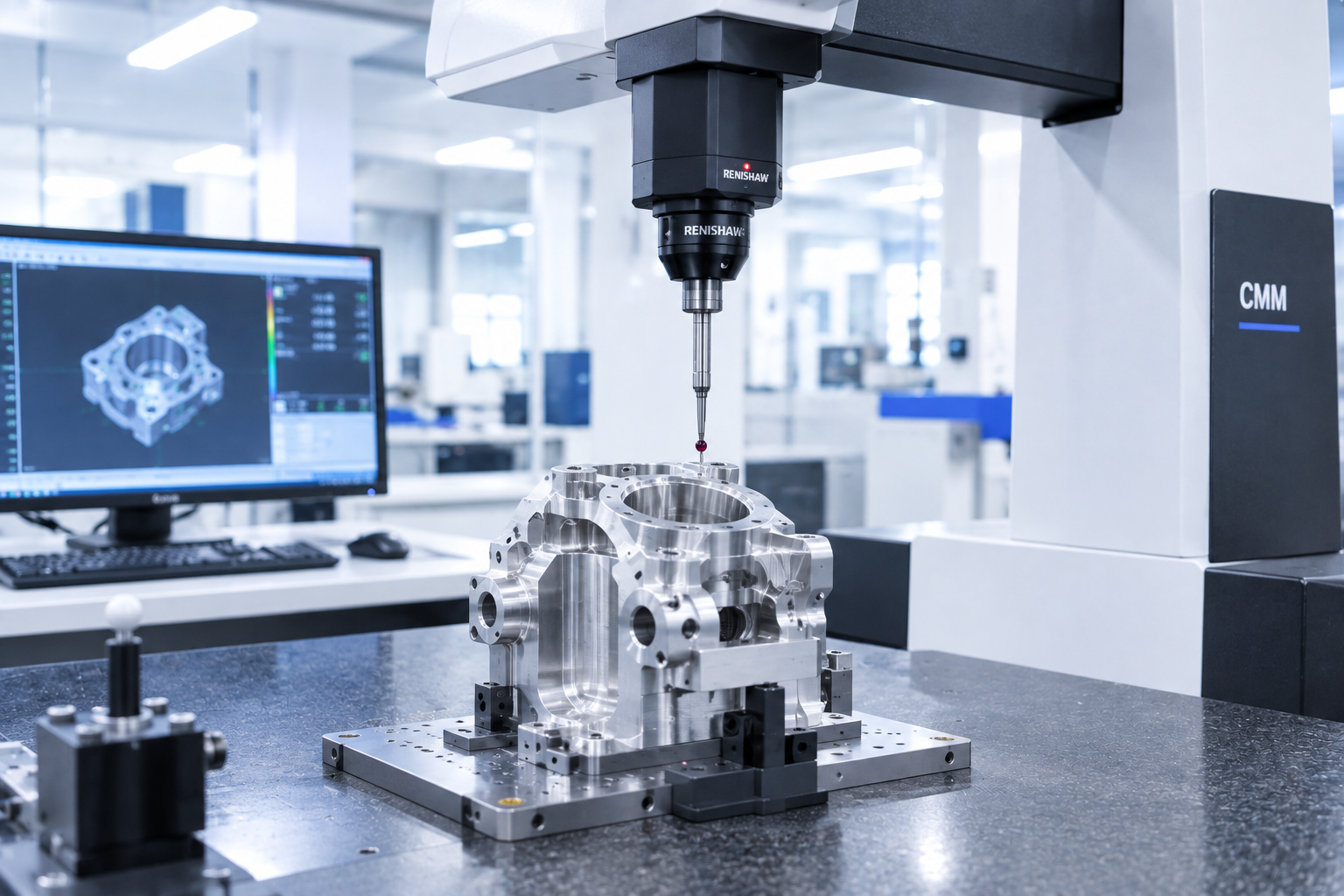
A Coordinate Measuring Machine, commonly known as a CMM, is used to measure the geometry of precision components.
A CMM uses a probe to collect dimensional data from multiple points on a part.
It can measure:
- Complex profiles
- Hole locations
- Angles
- Distances
- Geometric tolerances
- Surface coordinates
CMM inspection is particularly useful for complex or high-precision CNC components.
4. Optical Inspection
Optical inspection systems use cameras, lenses, or microscopes to measure small features without physically contacting the part.
They can be useful for:
- Small components
- Fine features
- Complex profiles
- Parts that are difficult to measure with contact tools
Optical measurement can also provide fast inspection for certain production applications.
5. Surface Roughness Inspection
Surface finish can be an important functional requirement for CNC machined components.
A surface roughness tester can measure parameters such as:
Ra — Average Surface Roughness
Surface finish requirements may be important for:
- Moving components
- Sealing surfaces
- Bearing interfaces
- Visible product surfaces
The required surface finish should be specified according to the actual function of the part.
Common CNC Inspection Tools
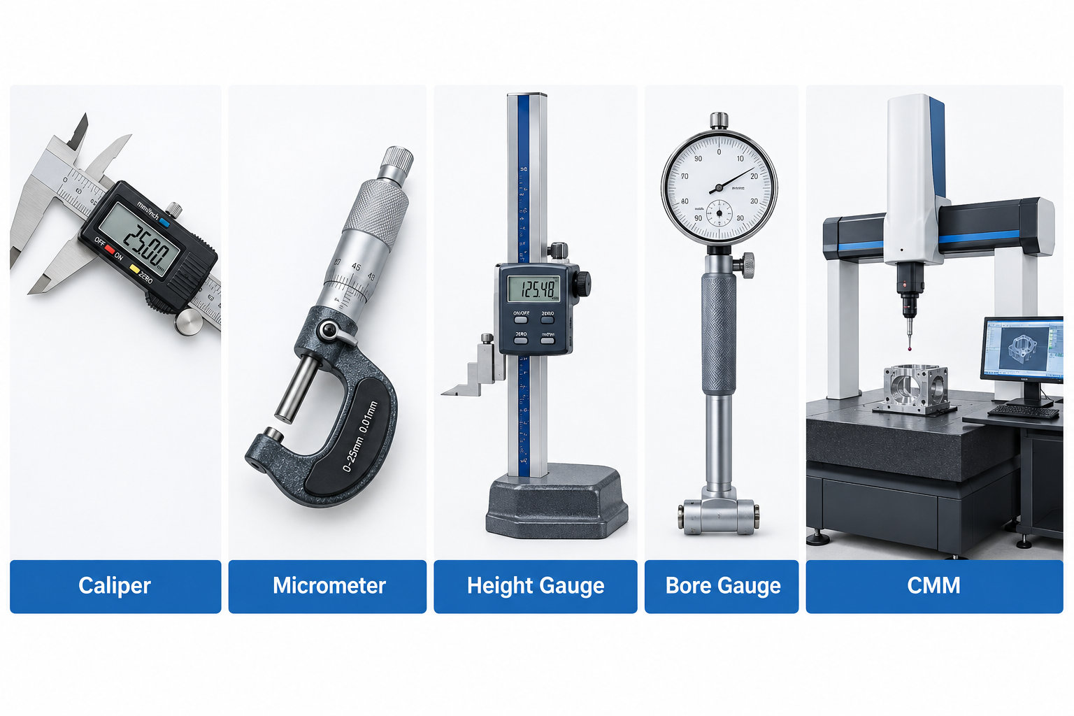
Different measurement tools are used depending on the required accuracy and geometry.
Calipers
Digital calipers are commonly used for general dimensional measurements.
They are useful for checking:
- Overall dimensions
- Outside diameters
- Inside dimensions
- Depths
They are generally suitable for general-purpose inspection rather than extremely tight tolerances.
Micrometers
Micrometers provide more precise dimensional measurements than standard calipers.
They are commonly used for measuring:
- Outside diameters
- Thickness
- Shafts
- Precision features
Different types of micrometers are available for different measurement applications.
Height Gauges
Height gauges are used to measure vertical dimensions and feature locations from a reference surface.
They can be particularly useful for checking:
- Hole locations
- Step heights
- Feature positions
Bore Gauges
Bore gauges are designed to measure internal diameters accurately.
They are useful for checking:
- Cylindrical holes
- Bearing bores
- Internal diameters
CMM
CMMs are among the most advanced inspection tools used in CNC manufacturing.
They are especially useful when a component contains multiple precision features that must be measured relative to one another.
CNC Inspection Process
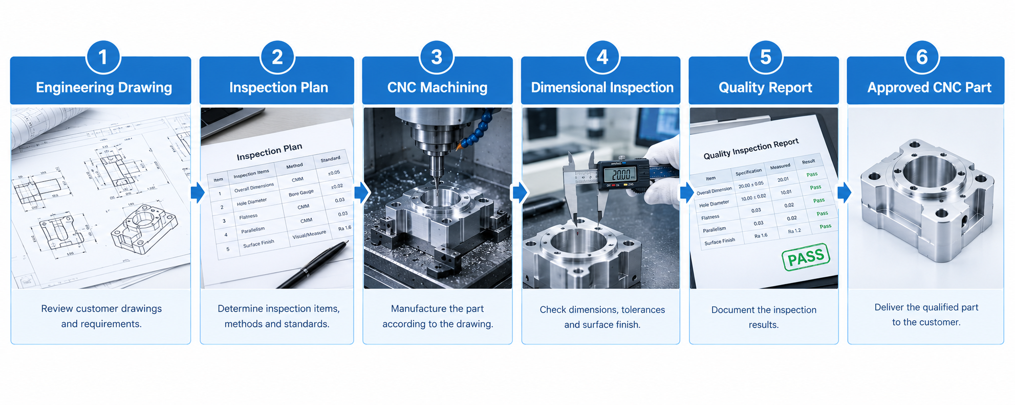
A typical inspection process may include several stages.
Step 1: Review Engineering Requirements
Before measuring the part, the inspector reviews:
- Engineering drawings
- CAD files
- Dimensions
- Tolerances
- Surface finish requirements
- Material requirements
This establishes the inspection criteria.
Step 2: Select Measurement Equipment
The appropriate inspection equipment is selected based on the required accuracy and feature geometry.
For example:
Caliper → General Dimensions
Micrometer → Precision Dimensions
Bore Gauge → Internal Diameter
CMM → Complex Geometry and GD&T
Step 3: Measure the Finished Part
The inspector measures the required features according to the inspection plan.
Critical dimensions may receive more detailed inspection than non-critical dimensions.
Step 4: Compare Results With Specifications
Measured values are compared with the engineering requirements.
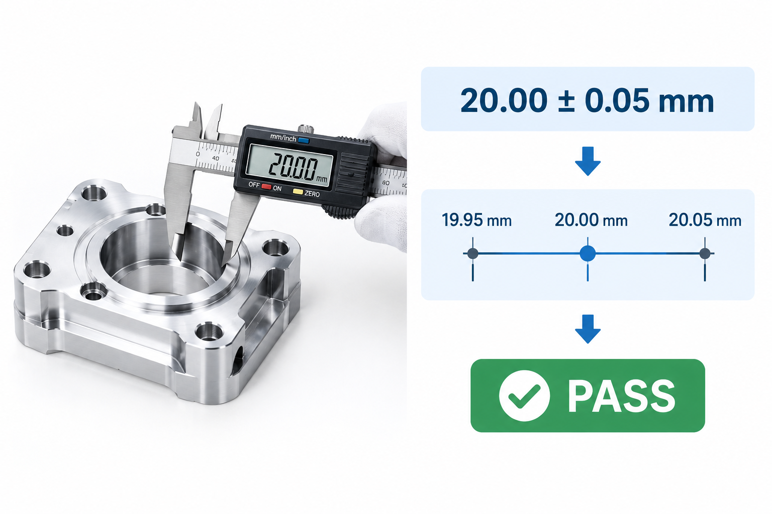
For example:
Specified Dimension
20.00 ± 0.05 mm
Acceptable Range
19.95–20.05 mm
If the measured value falls within the specified range, the dimension passes inspection.
Step 5: Record Inspection Results
Inspection results can be documented in an inspection report.
Depending on the customer’s requirements, the report may include:
- Measured dimensions
- Tolerances
- Actual values
- Pass/fail results
- Inspection equipment
- Inspector information
What Is GD&T in CNC Machining?
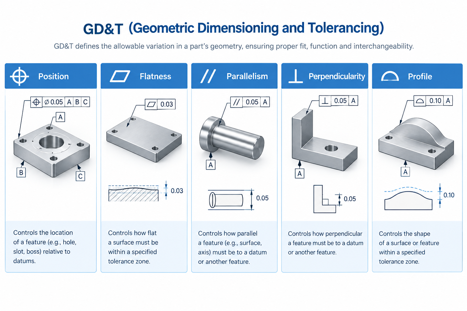
Geometric Dimensioning and Tolerancing, or GD&T, is a standardized system used to define allowable variation in the geometry of a component.
Unlike basic dimensional tolerances, GD&T can control characteristics such as:
- Position
- Flatness
- Parallelism
- Perpendicularity
- Concentricity
- Profile
GD&T is particularly useful for complex mechanical components where the relationship between different features is critical.
For example, two holes may individually have correct diameters but still be incorrectly positioned relative to each other.
GD&T provides a more complete way to control these relationships.
CNC Machining Inspection vs. Tolerance
Inspection and tolerance are closely related but serve different purposes.
A tolerance defines how much a dimension is allowed to vary.
Inspection verifies whether the manufactured part falls within that allowed range.
For example:
Nominal Size: 50.00 mm
Tolerance: ±0.05 mm
Acceptable Range: 49.95–50.05 mm
The inspection process determines whether the actual part falls within this range.
When Does a CNC Part Need CMM Inspection?
Not every CNC component requires CMM inspection.
CMM inspection may be appropriate when:
- Tight tolerances are required
- Multiple features must be measured relative to each other
- Complex 3D geometry is involved
- GD&T requirements are specified
- The component is used in a critical application
- Detailed dimensional documentation is required
For simple parts with standard tolerances, basic inspection equipment may be sufficient.
Choosing the appropriate inspection method can help control manufacturing costs without compromising quality.
How Inspection Affects CNC Machining Cost
Inspection is an important part of manufacturing, but more inspection does not necessarily mean better value.
Additional inspection requirements can increase:
- Labor time
- Equipment usage
- Documentation
- Production lead time
For example, a simple prototype may only require basic dimensional inspection, while a highly precise aerospace component may require detailed CMM inspection and comprehensive documentation.
The inspection level should therefore match the actual requirements of the component.
How to Improve CNC Machining Quality
Quality starts before the machining process begins.
Several factors can improve the consistency of CNC machined parts.
Use Clear Engineering Drawings
Clearly specify:
- Dimensions
- Tolerances
- Materials
- Surface finishes
- Critical features
Apply Realistic Tolerances
Avoid specifying extremely tight tolerances unless they are necessary.
Unnecessary precision can increase machining and inspection costs.
Use DFM Principles
Designing parts with manufacturing in mind can reduce machining difficulties.
Consider:
- Tool accessibility
- Wall thickness
- Internal radii
- Hole sizes
- Number of setups
Establish an Inspection Plan
Critical dimensions should be identified before production.
This allows manufacturers to determine the appropriate measurement methods and equipment.
CNC Inspection for Prototypes and Production Parts
Inspection requirements may change depending on production volume.
Prototype Parts
Prototype inspection may focus on:
- Critical dimensions
- Functional features
- Fit and assembly
- Design validation
Low-Volume Production
Inspection may include more systematic dimensional checks and inspection reports.
High-Volume Production
Production environments may use statistical quality control and process monitoring to maintain consistency across large numbers of parts.
The inspection strategy should match the production requirements and risk level of the component.
CNC Machining Inspection at KG Precise
At KG Precise, quality inspection is an important part of our CNC machining process.
Depending on project requirements, components can be inspected for:
- Dimensional accuracy
- Critical tolerances
- Feature locations
- Surface finish
- Overall appearance
Our engineering team can review your drawings and inspection requirements before production to determine an appropriate quality control process.
Whether you need a single prototype or low-volume production parts, we work to ensure that finished components meet the required specifications.
Upload your CAD file to request a quote.
Conclusion
CNC machining inspection plays an important role in ensuring that finished components meet their engineering requirements.
From basic calipers and micrometers to advanced CMM systems, different inspection tools are suited to different applications.
The right inspection method depends on the part’s geometry, tolerances, functional requirements, production volume, and quality standards.
By combining accurate CNC machining with an appropriate inspection process, manufacturers can produce reliable components while avoiding unnecessary inspection costs.
For precision CNC prototypes and low-volume production, working with an experienced manufacturing partner can help ensure that both machining and quality requirements are properly addressed.